Tech Stuff - RS-232 Cables, Wiring and Pinouts
Brief tutorial and pinouts for RS-232, RS422/485, T1/E1 and V.35. If you want to know more about RS 232 signals then this page may help - but you may also need to lie down in a darkened room afterwards.
Contents
- DTE (PC) and DCE (Modem)
- DB9 and DB25 Male and Female Pin Numbering
- RS232 on DB25 Pinout (RS-232C)
- RS232 on DB9 Pinout (TIA - 574)
- RS232 on RJ45 (RS-232D TIA-561)
- RS232 DB25 NULL Modem Pinout
- RS232 DB9 NULL Modem Pinout
- RS232 DB9 and DB25 Loopback Pinout
- RS232 DB9 NULL Modem Pinout using Cat5(e)
- RS232 DB9 to DB25 Pinout
- RS232 DB9 to DB25 NULL Modem Pinout
- RS-422, 423 and 485 TIA/RS-530-A using DB25)
- RS-422 and 485 using DB9
- V.35 on a DB25
- DBx - Designations for D type sub-miniature connectors
- T1/E1 Pinout (RJ-48C)
RS-232 standards(TIA-232) are defined by TIA (Telecommunications Industry Association). RS-232 defines both the physical and electrical characteristics of the interface. RS-232 is practically identical to ITU V.24 (signal description and names) and V.28 (electrical). RS232 transmit (TX and Receive (RX) are ACTIVE LOW voltage interfaces and operates at +12V to -12V where:
- Signal = 0 > +3.0V (SPACE)
- Signal = 1 < -3.0V (MARK)
Notes:
Signal voltages in the range >-3.0V to +3.0V are regarded as being in the 'dead area' (indeterminate value) and allow for absorption of noise. For more on the use of signals and other heavy stuff.
Control Signals (CTS, RTS, DTR, DSR etc. are ACTIVE HIGH (range +3V tp +12V). For more on the use of signals and other heavy stuff.
The power level on RS232 pins is defined by TIA for short circuit protection to be 100mA. Most RS232 drivers will provide lower short circuit protection (especially for laptops). A max of 50mA PER PIN may be available but the data sheet for the specific interface/chip should be consulted before commiting to externally powered designs.
We received an email recently pointing out some issues with NULL modem cables. The pinouts shown below will generally work. However, there are many permutations of signal sets that can be used by either end of a connection and they may not be SYMMETRIC. One end may expect something (a signal) that the other end cannot generate. This typically happens with CTS/RTS (and perhaps DCD) and DTR/DSR. If you suspect this is the case then unfortunately you need to understand the interface and may have to 'spoof' (artifically create) certain signals. Our signal primer page may help you. Finally, if you are having serious problems, splash out on what is frequently called a 'light box' or some other device that will show you which signals are being activated.
Serial communications equipment may be either a DTE (Data Terminal Equipment - a terminal or PC) or a DCE (Data Communications Equipment - for example, a modem) and have a direction depending on the type. All the diagrams below define the interface from the DTE perspective.
The terms Data Carrier Detect (DCD) and Received Line Signal Detect (RLSD) are one and the same. We use DCD throughout 'cos we think it's more common.
While the term RS232 is almost universally used these days for serial/modem connections, outside of North America it is quite common to come across the ITU designations V.24/V.28 when describing serial/modem communications. For all practical purposes RS232 and V.24/V.28 are identical.
Like most folks we use the term DB9 which is widely - but erroneously - coined to describe a 9-pin serial connector. We got an email pointing out the error of our ways (hint: it is really a DE-9P). So, if you want to amaze your friends over the dinner table, you can read more and use the technically correct terms in the future. While we get away with DB9 most of the time (with common or garden PCs), sometimes it is essential to know EXACTLY what connector type you are talking about. And, following a recent email request, we discovered that the thread on RS-232 (DB9 and 25) receptacles is UNC 4-40.
RS-232-E is normally defined to be used with a DB25 connector, but does have a 26 pin (a much smaller) alternative . We suggest that if you come across one of these that you do the decent thing - use an expletive. Alternatively, with your luck, you could consider buying a lottery ticket.
We have received a number of emails asking how to wire DB9's using cat5(e)/cat 6 cable. We guess there is a lot of LAN cable lying around these days (and its cheap) so folks naturally want to use it. We have added a null modem only section to cover this wiring. There is absolutely no standard to cover this form of wiring. This section is simply offered as one of many possible ways to do it. While we are on the topic of wiring, RS232 does not define a cable standard but this may help in choosing a suitable cable.
We got an email asking about TTY 20ma current loop interfaces. This was an old method used to connect teletype devices and uses current (normally 20ma but sometimes 60ma) to indicate mark and space. A TTY system CANNOT be connected to RS-232 (which is a voltage driven interface) and has no standard. You will need to get the manufacturer's specifications and start reading!
RS-232 is probably the most widely known serial standard because of its use in PCs. It uses unbalanced communications (single TX/RX/CTS/RTS connectors) and hence has both speed limitations and is susceptible to noise interference. RS-422 or RS-485 are increasingly common because they use balanced communication (two connectors for most signals) and provide higher speeds (up to 10 mbit/s) and are significantly more robust in electrically noisy environments - such as automotive, military, telecommunications and marine.
Like most people we continue to use the term RS, as in RS-232, RS-422, etc. Many moons ago the standardization effort was taken over by EIA/TIA (sometimes written as TIA/EIA). Now the EIA no longer exists (as of Feb 11th, 2011) and TIA is the only man left standing. Consequently, you will occasionally see references to TIA-232 or TIA-574 etc. Anything with a TIA designation is functionally identical to the same number with an RS designation, thus, TIA-232 = RS-232. We will continue to use the RS term simply because we think it is still more widely used and because old dog, new tricks.....
DTE (PC) and DCE (Modem)
In serial communications the terminal end (PC) is called the Data Terminal Equipment (DTE) and the modem end is called the Data Communications Equipment (DCE) as shown in the diagram below.
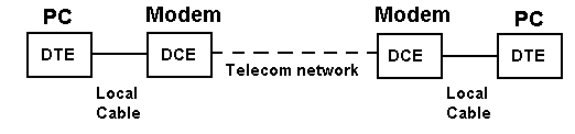
Serial Communications with a modem
RS-232 signals have a direction (in or out) depending on whether they are with respect to a DTE or a DCE. In all the pinout diagrams below the signal direction is with respect to the DTE (PC) end.
NULL Modem Connections
When PCs are connected back-to-back each end is acting as a DTE (there is no DCE in this case) and consequently certain signals may have to be looped in the connection to satisfy any input signal requirement. This is called a NULL (no) modem configuration. For example, when the DTE raises Request to Send (RTS) it typically expects Clear to Send (CTS) from the DCE. Since there is no DCE to raise CTS, the outgoing RTS signal is looped in the NULL modem cable to the incoming CTS to satisfy the DTE's need for this signal. This is shown in the diagram below.
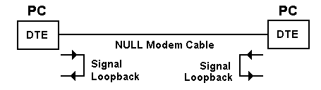
Serial Communications with a NULL modem configuration

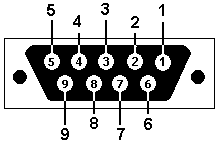
DB9 and DB25 Male and Female Pin Numbering
These diagrams show the male (grey background) and female (black background) pin numbering for DB9 and DB25 sub-miniature connectors. Generally Pin 1 is marked on the front of the connector right next to the pin - though you may need a magnifying glass to read it. Some manufacturers mark each pin number on the plastic housing at the rear of the connector. The male connector has the pins sticking out!
DB25 Male and Female
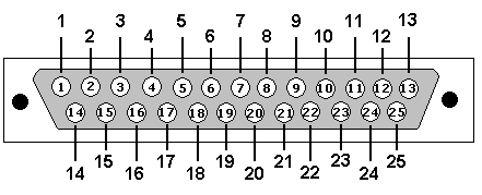
DB25: View looking into male connector
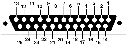
DB25: View looking into female connector
DB9 Male and Female
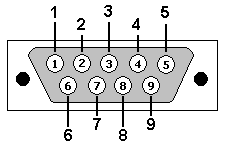
DB9: View looking into male connector
DB9: View looking into female connector
RS232 on DB25 (RS-232C)
The use of each pin including methods for spoofing signals is described in our Signal/pin primer. The RS-232 DB25 connector is capable of supporting two separate connections - each with its own optional clock when used in Synchronous mode or Bit-Synchronous mode. If you are using the interface purely for Asynchronous communications then you only need those marked with (ASYNC) below or you can use even fewer (if you understand what is happening). The column marked Dir shows the signal direction with respect to the DTE.
Note: This is NOT the same as the DB25 Parallel port on a PC.
| Pin No. |
Name |
Dir |
Notes/Description |
| 1 |
- |
- |
Protective/shielded ground |
| 2 |
TD |
OUT |
Transmit Data (a.k.a TxD, Tx) (ASYNC) |
| 3 |
RD |
IN |
Receive Data (a.k.a RxD, Rx) (ASYNC) |
| 4 |
RTS |
OUT |
Request To Send (ASYNC) |
| 5 |
CTS |
IN |
Clear To Send (ASYNC) |
| 6 |
DSR |
IN |
Data Set Ready (ASYNC) |
| 7 |
SGND |
- |
Signal Ground |
| 8 |
CD |
IN |
Carrier Detect (a.k.a DCD). |
| 9 |
- |
- |
Reserved for data set testing. |
| 10 |
- |
- |
Reserved for data set testing. |
| 11 |
- |
- |
Unassigned |
| 12 |
SDCD |
IN |
Secondary Carrier Detect. Only needed if second channel being used. |
| 13 |
SCTS |
IN |
Secondary Clear to send. Only needed if second channel being used. |
| 14 |
STD |
OUT |
Secondary Transmit Data. Only needed if second channel being used. |
| 15 |
DB |
OUT |
Transmit Clock (a.k.a TCLK, TxCLK). Synchronous use only. |
| 16 |
SRD |
IN |
Secondary Receive Data. Only needed if second channel being used. |
| 17 |
DD |
IN |
Receive Clock (a.k.a. RCLK). Synchronous use only. |
| 18 |
LL |
- |
Local Loopback |
| 19 |
SRTS |
OUT |
Secondary Request to Send. Only needed if second channel being used. |
| 20 |
DTR |
OUT |
Data Terminal Ready. (ASYNC) |
| 21 |
RL/SQ |
- |
Signal Quality Detector/Remote loopback |
| 22 |
RI |
IN |
Ring Indicator. DCE (Modem) raises when incoming call detected used for auto answer applications. |
| 23 |
CH/CI |
OUT |
Signal Rate selector. |
| 24 |
DA |
- |
Auxiliary Clock (a.k.a. ACLK). Secondary Channel only. |
| 25 |
- |
- |
Unassigned |
NOTE: Leave all pins not specified above unconnected.
view - looking into male connector
(male and female connector diagrams)
RS232 on DB9 (EIA/TIA 574)
Signal functions are described in detail in our Signal/pin primer. The column marked Dir shows the signal direction with respect to the DTE.
| Pin No. |
Name |
Dir |
Notes/Description |
| 1 |
DCD |
IN |
Data Carrier Detect. Raised by DCE when modem synchronized. |
| 2 |
RD |
IN |
Receive Data (a.k.a RxD, Rx). Arriving data from DCE. |
| 3 |
TD |
OUT |
Transmit Data (a.k.a TxD, Tx). Sending data from DTE. |
| 4 |
DTR |
OUT |
Data Terminal Ready. Raised by DTE when powered on. In auto-answer mode raised only when RI arrives from DCE. |
| 5 |
SGND |
- |
Ground |
| 6 |
DSR |
IN |
Data Set Ready. Raised by DCE to indicate ready. |
| 7 |
RTS |
OUT |
Request To Send. Raised by DTE when it wishes to send. Expects CTS from DCE. |
| 8 |
CTS |
IN |
Clear To Send. Raised by DCE in response to RTS from DTE. |
| 9 |
RI |
IN |
Ring Indicator. Set when incoming ring detected - used for auto-answer application. DTE raised DTR to answer. |
DB9 (EIA/TIA 574): View - looking into male connector
(male and female connector diagrams)
RS232 on RJ45 (RS-232D)
More properly EIA/TIA - 561. Use when connecting to or from a serial port with a 8 position Modular Jack (RJ45). If you are cross-connecting from a DB9 or a DB25 use the signal names to cross connect the appropriate pins. To illustrate the process the equivalent pins used for cross-connecting a DB9 connector signals are shown (see DB9 pin-out above).
Signal/pin primer
| RJ45 Pin No. |
Name |
DB9 Cross Connect |
Notes/Description |
| 1 |
DSR/RI |
6,9 |
Data set Ready/ring indicator |
| 2 |
DCD |
1 |
Data Carrier Detect |
| 3 |
DTR |
4 |
Data Terminal Ready |
| 4 |
SGND |
5 |
Signal Ground |
| 5 |
RD |
2 |
Receive Data |
| 6 |
TD |
3 |
Transmit Data |
| 7 |
CTS |
8 |
Clear to Send |
| 8 |
RTS |
7 |
Request to Send |
Note: Pin 1 is a multi-function pin sharing DSR (Data Set Ready) and RI (Ring Indicator). This means it is impossible to differentiate between a incoming ring signal (RI) and when the modem has finally connected and synched up (DSR). With local (null modem connections) or if the modem is run in auto-answer mode this is not normally a problem. If used with a modem and the DTE (the computer end) wants to control the connection the problem is more real. DSR would normally indicate the 'connected and synched-up' state following DTR from the DTE whereas RI simply indicates a ring voltage is present on the line and would normally be the trigger for the DTE to raise DTR if it wants to accept the call. DCD will indicate that a carrier has been received but does not indicate synchronization of both ends. In most cases however CTS (Clear To Send) in response to RTS (Request To Send) will not normally be returned until an end-to-end connection is available (equivalent to the DSR state).
RJ45 Male Connector Pin Numbering
RS232 DB25 NULL Modem Pinout
Use when connecting two systems (e.g. PCs) via their DB25 interfaces without a modem (i.e. back-to-back). See the full signal names in the DB25 sections.
If this pinout does not work for you then you could try our Signal/pin primer because you may need to SPOOF connections.
Note: This DB25 is NOT the same as the DB25 Parallel port on a PC which is defined here.
| DB25 |
Signal |
DB25 |
Signal |
| 3 |
RD |
2 |
TD |
| 2 |
TD |
3 |
RD |
| 20 |
DTR |
6,8 |
DSR, DCD |
| 6,8 |
DSR, DCD |
20 |
DTR |
| 4 |
RTS |
5 |
CTS |
| 5 |
CTS |
4 |
RTS |
| 7 |
SGND |
7 |
SGND |
| 22 |
RI |
22 |
RI |
DB25: View - looking into male connector
(male and female connector diagrams)
NOTE:
Leave all pins not specified above unconnected.
We have received email suggesting that the above pinout looks like DTR from one side is driving into DSR/DCD on the other side - not normally a healthy situation. The emails miss the point that since this is a NULL modem connection both ends are DTEs. The two peer DTE's treat DSR/DCD signals as RX (INPUT) only. The INPUT DSR/DCD on one side is created by cross connecting the OUTPUT DTR signal for the other peer.
RS232 DB9 NULL Modem Pinout
Use when connecting two systems, for example two PCs, via their DB9 interfaces without a modem. Typically called a back-to-back or NULL modem connection. See the full signal names in the DB9 section.
If this pinout does not work for you then you could try our Signal/pin primer because you may need to SPOOF connections.
| PC1 Peer |
PC2 Peer |
| DB9 Pin |
Signal |
DB9 Pin |
Signal |
| 2 |
RD |
3 |
TD |
| 3 |
TD |
2 |
RD |
| 4 |
DTR |
6,1 |
DSR, DCD |
| 6,1 |
DSR, DCD |
4 |
DTR |
| 7 |
RTS |
8 |
CTS |
| 8 |
CTS |
7 |
RTS |
| 5 |
SGND |
5 |
SGND |
| 9 |
RI |
9 |
RI |
DB9 TIA/EIA 574: View - looking into male connector
(male and female connector diagrams)
NOTE:
We have received email suggesting that the above pinout looks like DTR from one side is driving into DSR/DCD on the other side - not normally a healthy situation. The emails miss the point that since this is a NULL modem connection both ends are DTEs. The two peer DTE's treat DSR/DCD signals as RX (INPUT) only. The INPUT DSR/DCD on one side is created by cross connecting the OUTPUT DTR signal for the other peer.
RS232 DB9 and DB25 Loopback Pinout
Loopback is a method of testing the RS232 connector and interface circuitry to ensure it is functioning correctly, that is, in layman's jargon - it ain't broke! If communication fails to occur between two machines the question that immediately arises is - which end is broken? In the worst case both ends could even be broken in which case ritual suicide may be the best solution. Loopback works by testing each end of the connection independently. Data is sent and received on the same RS232 connector - which may be either DB9 or DB25. The test normally consists of using some program to transmit data. The program then checks to ensure exactly the same data was received. Loopback testing gives you a binary result - it works, in which case the end under test is good, or it does not, in which case the end under test is broken. Pinouts are shown for both DB9 and DB25. The loopback is normally constructed in the DB shell or using a diagnostic light-box.
DB9 Loopback
| DB9 |
Signal |
Loopback to |
Signal |
| 2 |
RD |
3 |
TD |
| 3 |
TD |
2 |
RD |
| 4 |
DTR |
6,1,9 |
DSR, DCD, RI |
| 7 |
RTS |
8 |
CTS |
| 5 |
SGND |
5 |
SGND |
(DB9 male and female connector diagrams)
NOTE:
We show 4 (DTR) being looped to 6 (DSR), 1 (DCD) and 9 (RI). RI (9) is included because we understand that certain test programs use this to ensure a more complete test of the interface signal set.
DB25 Loopack
| DB25 |
Signal |
Loopback to |
Signal |
| 3 |
RD |
2 |
TD |
| 2 |
TD |
3 |
RD |
| 4 |
RTS |
5 |
CTS |
| 5 |
CTS |
4 |
RTS |
| 7 |
SGND |
7 |
SGND |
| 15 |
DB |
17 |
DD |
| 20 |
DTR |
6,8,22 |
DSR, DCD, RI |
| 23 |
CH/CI |
23 |
CH/CI |
(male and female connector diagrams)
NOTE:
For the sake of simplicity this loopback will only work for the primary channel. Full DB25 interfaces allow a secondary channel. If a complete interface loopback is required you will need to add pins 12, 13, 14, 16, 19, 24.
By looping the primary channel clocks (15 and 17) both synchronous and asynchronous capabilities can be tested. If only asynchronous tests are being performed omit this, and the pin 23 loopback
We show 20 (DTR) being looped to 6 (DSR), 8 (DCD) and 22 (RI). RI (22) is included because we understand that certain test programs use this to ensure a more complete test of the interface signal set.
RS232 DB9 NULL Modem Pinout on CAT5/CAT5(e)/CAT6
This is in response to a number of recent emails asking how to wire both ends of a DB9 connection using cat5, cat5(e) or cat6 cable. This must not be confused with DB9 to RJ45 (RS232D). We have shown a null modem (back-to-back PCs) only configuration. And if you want to use cat5, cat5(e) or cat 6 with a real modem (a DB25 connector)? Our advice - don't.
Warning:. There is, as far as we know, no standard to cover the use of cat5, cat5(e) or cat 6 (8 conductor) wiring when used with two DB9 connectors. Any such wiring scheme is therefore non-standard - that includes the wiring scheme below. Specifically this means that both ends of the cable must be wired in the same way and that no assumptions can be made about how the other end is wired. You will have to manually inspect both ends of the connection. Damage can result from mis-matched wiring.
A DB9 clearly has 9 connections and a cat5, cat5(e) and cat 6 cable has 8 conductors. RS232D has chosen to use Pin 1 as a multi-function pin (DSR/RI) to provide maximum flexibility with modems - in particular it allows for DCD which is a meaningful signal from a modem but not, we suggest, from a peer PC. We have chosen to use a minor variation on the normal DB9 Null modem pinout above - specifically we have allowed for RI which could be used from a peer PC to commence a transmission sequence. The colors used are unimportant but the suggested configuration is one way to provide the shortest use of the adjacent (twisted) pairs.
If this pinout does not work for you then you could try our Signal/pin primer because you may need to SPOOF connections.
| PC1 Peer |
PC2 Peer |
| DB9 |
Signal |
cat5(e)
Color |
DB9 |
Signal |
cat5(e)
Color |
| 2 |
RD |
Brown |
3 |
TD |
Blue |
| 3 |
TD |
Blue |
2 |
RD |
Brown |
| 4 |
DTR |
Green |
6,1 |
DSR, DCD |
Brown-white |
| 6,1 |
DSR, DCD |
Brown-white |
4 |
DTR |
Green |
| 7 |
RTS |
Blue-white |
8 |
CTS |
Green-white |
| 8 |
CTS |
Green-white |
7 |
RTS |
Blue-white |
| 5 |
SGND |
Orange |
5 |
SGND |
Orange |
| 9 |
RI |
Orange-white |
9 |
RI |
Orange-white |
DB9: View - looking into male connector
(male and female connector diagrams)
NOTE:
We have received email suggesting that the above pinout looks like DTR from one side is driving into DSR/DCD on the other side - not normally a healthy situation. The emails miss the point that since this is a NULL modem connection both ends are DTEs. The two peer DTE's treat DSR/DCD signals as RX (INPUT) only. The INPUT DSR/DCD on one side is created by cross connecting the OUTPUT DTR signal for the other peer.
RS232 DB9 to DB25 Pinout
Use when connecting a DB9 (e.g. a PC) to a DB25 (e.g. a modem) interface. See the full signal names in the DB9
and DB25 section.
Signal/pin primer
| DB9 |
Signal |
DB25 |
| 1 |
DCD |
8 |
| 2 |
RD |
3 |
| 3 |
TD |
2 |
| 4 |
DTR |
20 |
| 5 |
SGND |
7 |
| 6 |
DSR |
6 |
| 7 |
RTS |
4 |
| 8 |
CTS |
5 |
| 9 |
RI |
22 |
View - looking into male connector
(male and female connector diagrams)
View - looking into male connector
(male and female connector diagrams)
NOTE: Leave all pins not specified above unconnected.
RS232 DB9 to DB25 NULL Modem Pinout
Use when connecting two systems (e.g. PCs) when one has a DB9 interface and the other a DB25 interface without a modem. Typically called a back-to-back or NULL modem connection. See the full signal names in the DB9
and DB25 sections.
Signal/pin primer
| DB9 |
Signal |
DB25 |
Signal |
| 2 |
RD |
2 |
TD |
| 3 |
TD |
3 |
RD |
| 4 |
DTR |
6,8 |
DSR, DCD |
| 6,1 |
DSR, DCD |
20 |
DTR |
| 7 |
RTS |
5 |
CTS |
| 8 |
CTS |
4 |
RTS |
| 5 |
SGND |
7 |
SGND |
| 9 |
RI |
22 |
RI |
DB9: View - looking into male connector
(male and female connector diagrams)
View - looking into male connector
(male and female connector diagrams)
Note: Leave all pins not specified above unconnected.
RS-422, RS423 and RS-485 (TIA/RS-530-A using DB25)
RS 530-A defines the pinout when using either balanced RS-422 (and RS-485) or unbalanced RS-423 using a DB25 connector. The A (+) and B (-) below refer to each signal pair used in balanced serial interfaces (A+ is non-inverting, B- is inverting). When used with RS-423 (unbalanced) the B (-) are tied to a common ground. Signals marked U under Bal/Ubal are not balanced since they typically change very infrequently (for example once per session) and therefore do not affect TX/RX performance sensitivity - hence speed. BEWARE: RS-530 (without the A suffix) is an earlier standard and is wired differently (in particular both DTE Ready/DTR and DCE Ready/DSR used balanced communications - two pins). This is the RS-530-A pinout spec in which DTE Ready/DTR, DCE Ready/DSR are unbalanced and RI is introduced on Pin 22. The pinout supports both synchronous (V.35/v.10/V.11) which require clocks and aynchronous systems (RS-422/RS-485) which do not require clocks. The column marked 422/485 indicates the signals required for these interfaces - all others are N.C. (Not connected). RS422/485 on a DB9 is separately defined.
RS-422 vs RS-485: Many of us get confused over the difference between RS-422 (multi-drop) and RS-485 (multi-point). RS-422 allows only one master (or transmitter) all others are only receivers.
Notes:
MIL-STD-188-114B reportedly does interwork with RS-422/485.
| Pin No. |
RS Signal Name |
Bal/Ubal |
422/485 |
Notes |
| 1 |
Shield |
|
Y |
Cable Shield, connected at DTE only. |
| 2 |
Transmit Data (A+) |
|
Y |
a.k.a TxD |
| 3 |
Received Data (A+) |
|
Y |
a.k.a. RxD |
| 4 |
RTS (A+) |
|
Y |
Request To Send |
| 5 |
CTS (A+) |
|
Y |
Clear To Send |
| 6 |
DCE Ready (modem/CSU) |
U |
Y |
a.k.a DSR |
| 7 |
Signal Ground |
|
Y |
- |
| 8 |
Data Carrier Detect (A+) |
|
Y |
a.k.a DCD, CD or RLSD |
| 9 |
Receiver Signal Element Timing (B-) |
|
|
RX Clock |
| 10 |
Data Carrier Detect (B-) |
- |
Y |
a.k.a DCD, CD or RLSD |
| 11 |
Ext. Transmit Clock (B-) |
- |
|
- |
| 12 |
Transmit Signal Element Timing (B-) |
|
|
TX CLOCK |
| 13 |
CTS (B-) |
|
Y |
Clear to Send |
| 14 |
Transmit Data (B-) |
|
Y |
a.k.a TxD |
| 15 |
Transmit Signal element Timing (A+) |
|
|
TX CLOCK |
| 16 |
Received Data (B-) |
|
Y |
a.k.a RxD |
| 17 |
Receiver Signal Element Timing (A+) |
|
|
RX CLOCK |
| 18 |
Local Loopback |
U |
|
|
| 19 |
RTS (B-) |
|
Y |
Request to Send |
| 20 |
DTE Ready |
U |
Y |
a.k.a DTR |
| 21 |
Remote Loopback |
U |
|
- |
| 22 |
Ring Indicator |
|
Y |
RI |
| 23 |
Signal Ground |
|
Y |
- |
| 24 |
Ext TX Clock (A+) |
|
|
- |
| 25 |
TM |
U |
|
Test Mode |
RS-422 and RS-485 (DB9)
There is no official standard for using RS-422 or RS-485 on a DB9. The following pinout is widely used by many manufacturers but you are advised to verify with the manufacturer's specifications before proceeding. The following pinout provides no features for signaling end-to-end equipment readiness (for example DTE Ready/DTR and DCE Ready/DSR - see RS422/485 on DB25). Software drivers must use the CTS/RTS signals to indicate the presence and readiness of the peer.
Notes:
The A (+) and B (-) below refer to each signal pair used in balanced serial interfaces (A+ is non-inverting, B- is inverting).
| DB9 Pin |
Signal |
Notes |
| 1 |
Ground |
|
| 2 |
CTS (A+) |
Clear to Send |
| 3 |
RTS (A+) |
Request to Send |
| 4 |
Receive Data (A+) |
RxD |
| 5 |
Receive Data (B-) |
RxD |
| 6 |
CTS (B-) |
Clear To Send |
| 7 |
RTS (B-) |
Request to Send |
| 8 |
Transmit Data (A+) |
TxD |
| 9 |
Transmit Data (B-) |
TxD |
V.35 on DB25 (RS-530-A)
The original V.35 specification defined use of balanced signals over a huge 35 pin connector. V.35 has been obsolete for years (replaced with V.10) though the term is still frequently used. Most modern systems that call themselves V.35 use a DB25 connector which has more modest dimensions and uses the RS-530-A pinout scheme and maps the V.35 signal names to the RS-530-A names for convenience. The A (+) and B (-) below refer to each signal pair used in balanced serial interfaces (A+ is non-inverting, B- is inverting). Signals marked U under Bal/Ubal are not balanced since they typically change very infrequently (for example once per session) and therefore do not affect TX/RX performance sensitivity - hence speed. BEWARE: RS-530 (without the A suffix) is an earlier standard and is wired differently (in particular both DTE Ready/DTR and DCE Ready/DSR used balanced communications - two pins). This is the RS-530-A pinout spec in which DTE Ready/DTR, DCE Ready/DSR are unbalanced and RI is introduced on Pin 22. The signal names used in the pinout below refer to the standard (original) V.35 spec.
Signal/pin primer
| Pin No. |
V.35 Name |
Bal/Ubal |
Notes/RS Signal Name |
| 1 |
Shield |
|
Cable Shield, connected at DTE only. |
| 2 |
BA |
|
Transmit Data (A+) (a.k.a TxD) |
| 3 |
BB |
|
Received Data (A+) (a.k.a. RxD) |
| 4 |
CA/CJ |
|
RTS (A+) Request To Send |
| 5 |
CB |
|
CTS (A+) Clear To Send |
| 6 |
CC |
U |
Data Communications Equipment Ready (modem/CSU) (a.k.a DSR) |
| 7 |
AB |
|
Signal Ground |
| 8 |
CF |
|
Data Carrier Detect (A+) (a.k.a DCD, CD or RLSD) |
| 9 |
DD |
|
Receiver Signal Element Timing (B-) RX Clock |
| 10 |
CF |
- |
Data Carrier Detect (B-) (a.k.a DCD, CD or RLSD) |
| 11 |
DA |
- |
Ext. Transmit Clock (B-) |
| 12 |
DB |
|
Transmit Signal Element Timing (B-) TX CLOCK |
| 13 |
CB |
|
CTS (B-) Clear to Send |
| 14 |
BA |
|
Transmit Data (TD) (B-) (a.k.a TxD) |
| 15 |
DB |
|
Transmit Signal element Timing (A+) TX CLOCK |
| 16 |
BB |
|
Received Data (B-) (a.k.a RxD) |
| 17 |
DD |
|
Receiver Signal Element Timing (A+) RX CLOCK |
| 18 |
LL |
U |
Local Loopback |
| 19 |
CA/CJ |
|
RTS (B-) Request to Send |
| 20 |
CD |
U |
DTE Ready (a.k.a DTR) |
| 21 |
RL |
U |
Remote Loopback |
| 22 |
|
|
RI Ring Indicator |
| 23 |
AC |
|
Signal Ground |
| 24 |
DA |
|
Ext TX Clock (A+) |
| 25 |
TM |
U |
Test Mode |
NOTES:
- Leave any pins not specified above unconnected.
- In balanced mode signals with the same name are the paired set, for example, pins 2 and 14 are both named BA and form the Transmit Data pair. Each signal of the pair is either a high (A+) or low (B-)
- When used with RS-485 in half-duplex, multi-dropped environments a simple three signal arrangements is frequently used - one pin is used as a GND and RX/TX is alternately switched onto a balanced pair of wires which can be either the BA (TX) or BB (RX) pair.
View - looking into male connector
(DB25 male and female connector diagrams)
DB - Designations for D-subminiature Connectors
This lists the designations for DB connectors (supplied by Rob Recny - Thanks). Any errors in this list are ours not Rob's.
A - 15-pin 2-row joystick connector.
B - 25-pin 2-row serial or parallel connector - also 44-pin high-density 3-row.
C - 37-pin connector - sometimes found on multi-port serial or data acquisition boards.
D - 50-pin connector - a little longer than C, but three rows using the same pins as the 2-row connectors.
E - 9-pin 2-row serial - also 3-row VGA.
So a DB9 is more properly a DE-9P. Isn't knowledge a wonderful thing!
The thread size on an RS232 receptacle (the jackscrew) is UNC 4-40.
T1/E1 Pinout (RJ-48C)
T1/E1 wiring may use either a RJ45, DB15 or BNC connectors. The pinout shown uses RJ45 connectors - its formal name is USOC RJ-48C and is defined in ANSI T1-403-1989. T1 is a North America (primarily) digital service providing 1.544 Mbps. E1 is a European/Rest of World standard providing digital service at 2.048 Mbps. CATegory 5(e) cabling is used to provide balanced pairs. The color coding for Cat 5(e) cabling may be 568A or 568B.
| RJ45 Pin |
Signal |
Notes |
| 1 |
RX1 (Ring - negative) |
|
| 2 |
RX2 (TIP - positive) |
|
| 3 |
FGND (RX GND) |
Ground/Shield |
| 4 |
TX1 (Ring - negative) |
|
| 5 |
TX2 (TIP - positive) |
|
| 6 |
FGND (TX GND) |
Ground/Shield |
| 7 |
NC |
Unused |
| 8 |
NC |
Unused |
NOTES:
- NC = Not connected.
- There are a confusing number of pinouts for use with an RJ45/48C connector. Some specs show use of pins 7,8 for Grounds. Always consult any equipment specification if available.
- The telecom world loves its Tip and Ring designations. Tip is assumed to carry a positive voltage (and would carry the transmission signal), Ring a negative voltage (and would carry the inverted transmission signal)
Problems, comments, suggestions, corrections (including broken links) or something to add? Please take the time from a busy life to 'mail us' (at top of screen), the webmaster (below) or info-support at zytrax. You will have a warm inner glow for the rest of the day.


