Tech Stuff - Serial Interface Primer
A short, but generally happy, tale concerning the trials and tribulations of joining two PCs together with a bit of wire (a.k.a serial cable) to enable a true exchange of information - otherwise known as, RS-232 serial communications.
The page also contains merifully brief explanations of asynchronous, synchronous and bit-syncychronous communications and some notes on balanced and unbalanced connections.
Contents
A mercifully short serial primer covering:
- Serial pin functions
- Flow Control (CTS/RTS)
- Spoofing Flow Control (CTS/RTS)
- Start-up (DTR/DSR)
- Spoofing DTR/DSR
- Serial Comms Overview
- Asynchronous
- Synchronous
- bit-synchronous
- Balanced Serial Interfaces
- Unbalanced Serial Interfaces
<grovelling apology> Our description of the use of DSR and DTR in previous versions of this page was frankly misleading, bordering on wrong. The page has been updated and the use and function of these signals clarified. Thanks to Steve O'Brien for pointing out the error of our ways. </grovelling apology>
Serial Signal functions
This is not meant to be an exhaustive description of all the signals used in serial communications but rather a brief overview of the functionality of TD (Transmit Data), RD (Receive Data), CTS (Clear to Send), RTS (Request to Send), DSR (Data Set Ready) and DTR (Data Terminal Ready) signals to assist in building cables that, with a good following wind and rolling downhill, will generally tend to work.
For the purposes of this primer we concentrate on joining two Windows PCs (with great apologies to all us non-windows desktop users) using a NULL modem connection. A NULL modem connection just means there is no modem between the two PCs. The connection is assumed to be using the PC's DB9 ports with Asynchronous communications. If you are using real modems (not a NULL modem connection) the principles are the same but you need to consider additional signals such as DCD and RI. The key point to remember is that both the PCs are DTEs (Data Terminal Equipment) and were originally designed to be connected to a DCE (Data Communication Equipment - typically a modem). Signal Spoofing is the process of convincing (fooling) either or both ends into having a sensible conversation when both think they are talking to something entirely different.
Note: The terms 'raise' or 'raising' a signal appear throughout the following descriptions since they are a widely used slang when working in the dark arts of serial communications. 'Raised' means TRUE or ACTIVE which means supplying a voltage in the range > 3.0V < 12.0V.
Notes:
The RS 232 standards allow voltages in the range +-3V to +=15V. For historic reasons +-12V was most frequently used (+-5V is increasingly common).
The signals TX and RX are ACTIVE LOW (-12V to -3V Mark) whereas the control signals are ACTIVE HIGH (+3V to +12V = asserted or ON).
The Bare Minimum of signals
Yes, you can build a cable with only three pins connected (TD, RD and SGND) - see Figure 1 - and it may even work - typically if Flow control is set to 'none' in the Windows Serial Control Panel for the COM port at both ends.
Figure 1 - Minimal 3 pin cable

Flow Control (CTS/RTS)
The above cable has no Flow Control mechanism. Flow Control describes the process by which one end asks for permission from the other end before it transmits data. In systems where traffic is one way only, for example, a mouse, this is not an issue. However, if you set Flow control in the Control Panel for the COM port at both ends to 'hardware' then the PC's serial chip will ask for permission to send data (by raising RTS - Request To Send) and waiting for permission (CTS - Clear To Send) from the other end. A cable incorporating this functionality looks like Figure 2 - we 'cross' the RTS and CTS signals.
Figure 2 - Minimal 3 pin cable - with crossed CTS/RTS
It Gets Worse
Just as you think you understand everything, it can get worse. Suppose one end does not (or cannot) generate a CTS (the equivalent of Flow control in Control Panel set to 'none') but the other end needs it in response to its RTS ( equivalent of Flow Control in the Control Panel set to 'hardware')? Well, there is no limit to mankind's ingenuity. We are going to create a cable that spoofs the RTS/CTS by using a loop-back technique so that when one end raises RTS it immediately gets a CTS (actually its own looped RTS). In Figure 3 PC1 needs RTS/CTS but PC2 cannot generate it (and therefore does not need it).
Figure 3 - Minimal 3 pin cable - with looped (or spoofed) CTS/RTS for PC1
Getting it all Started
Sometimes communication will only start when both ends detect the presence of an active terminal or device. This is usually done by waiting for DTR (Data Terminal Ready) from the other end (which appears locally as DSR Data Set Ready) - or most unusually by waiting for DCD (Data Carrier Detect) indicating a synchronized modem carrier connection. Systems that require DSR will typically also raise Data Terminal Ready (DTR) to indicate they are rarin' to go but are just waiting for the other guy. The cable in Figure 4 will provide this functionality (by crossing DTR and DSR).
Figure 4 - Minimal 3 pin cable with crossed DTR/DSR and crossed CTS/RTS
Let's Wait - Forever
Now lets assume that one end does not (or cannot) generate DTR but the other end needs DSR before it will start to communicate. We will wait - forever - unless we get out the soldering iron and use our spoofing technique again. In the cable below we assume that PC1 needs DSR (and raises DTR) but PC2 does not need either signal. In order to illustrate yet another technique the cable in figure 5 has also looped the DSR signal to DCD (Data Carrier Detect) as well as DTR. DCD MAY be required by very picky systems and will do no harm in any case. The DCD connection can be omitted.
Note: If DTR is NOT raised by PC1 in this scenario you have a problem because DSR and DCD require a permanent LOW (RS232 is an active LOW interface) and you will need a steady > + 3V < 12V low current source to provide it.
Figure 5 - Minimal 3 pin cable with crossed CTS/RTS and spoofed DCD, DTR, DSR for PC1
We Ain't Done Yet
It really can get worse than this. The permutations are almost endless (Ah! the joy of serial communications) but the above techniques should allow you to create the cable you need to get that sucker rollin'.
Synchronous, Asynchronous and Bit-Synchronous
A brief overview of the most common serial communication systems.
Asynchronous
Asynchronous systems are the most common standard for serial communications and include your classic internet dial up modem systems. Asynchronous systems are character oriented. They send one character at a time. Asynchronous systems assume that both ends of the link are configured EXACTLY the same and each CHARACTER has enough information to allow the receiver to figure out when a character STARTS and STOPS (there are auto-bauding techniques which use a repetitive character, normally e, to figure out the settings automatically).
Asynchronous systems always have a single START bit and then allow a confusing number of variations including the number of bits in a character (5, 6, 7 or 8 bits), the number of stops bits used (1, 1.5 or 2) and an optional parity bit. Today, the most common standard is 8 bit characters, with 1 stop bit and no parity and this is frequently shortened to 8-1-n (or even 8-n-1). A single 8 bit character using 8-1-n (or even 8-n-1) therefore consists of 10 bits on the line = 1 START bit, 8 data bits and 1 STOP bit as shown in the diagram below.
Figure 6 - Asynchronous 8-n-1 serial communications
Notes:
Because the individual characters are framed (they contain enough data for the receiver to detect the start and end), unlike all the other systems described below, no CLOCK data is required or sent between the two ends and hence the pin-count can be kept very low - think DB9 or RJ45.
In most serial communications systems the Least Significant Bit (right-most) within each character is sent first. Thus, the 8 bit character whose binary pattern is 0110 0101 (65 hex or the character 'e') will appear on the line as 1010 0110.
RS-232/V.24 use Non Return to Zero (NRZ) encoding on the line as shown above. In this encoding, if the following bit is the same, no level transition occurs.
The gap between characters may be any length and may be either mark (high) or space (low) as shown, though in RS-232 the gap is always 'mark'.
Figure 6 shows logical values only. As previously described when data is sent or received it uses the signals TX and RX which are ACTIVE LOW (-12V to -3V Mark) whereas the control signals (CTS/RTS/DSR/DTR etc.) are ACTIVE HIGH (+3V to +12V = asserted or ON).
Finally: For the insatiably curious, and those that like to see stuff, Figure 7 shows an annotated scope trace illustrating the transmission of the english word 'Adam' using RS-232. The use of NRZ encoding is clearly visible in the trace (see note 3). While the space between characters in this trace is consistent there is no requirement for this to be true since each character is delimited by a start and stop bit (see notes 1 and 4). Many thanks to Vic Kovacs for taking the time to supply this trace which is provided under a Creative Commons Attribution-NonCommercial-ShareAlike Licence.
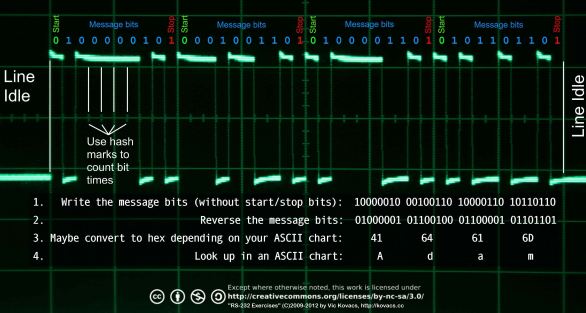
Figure 7 - Scope Trace of 'Adam' on RS-232 link
Synchronous
Synchronous systems are sometimes called block mode because communication is in blocks (not characters as in Asynchronous systems). Individual blocks are delimited with special characters called Control Characters, for example, in IBM Bi-Sync systems (and many others) by STX (Start of Text), ETX (End of Text). In order to allow the receiver time to synchronise, the block is normally preceded with one or more SYN Control characters. The block is almost always terminated with a Cyclic Redundancy Check (CRC) which is normally 16 bits, but can be 32 bits long.
Synchronous systems transmit a CLOCK (actually two clocks, one each for transmit and receive) with the data otherwise the far end could lose synchronisation during reception of a very long block (the transmitter and receiver clocks need not be exactly the same value). The requirement for a CLOCK signal means that Synchronous systems need to use a DB25 connector, a DB9 connector does not provide (and does not have enough pins for) a CLOCK signal.
Using 'special' or Control characters such as STX gives us a little problem if we want to send data which includes a value that happens to be same as a STX (or any of the other Control characters). This problem is called data transparency. The bi-sync family of protocols provides for this by the use of a special Control character (DLE) placed before the offending character, so the sequence DLE STX is interpreted as a data character STX not a Control character (the DLE is discarded by the receiver) and STX without a preceding DLE is a 'real' STX. The same rule applies to any other Control character including DLE, that is, DLE DLE sends a transparent character with the value of DLE. Synchronous data transmission is shown in Figure 8.
Figure 8 - Synchronous communications
Bit-Synchronous
Bit-Synchronous system represent the pinnacle of achievement in the serial world. HDLC, X.25 and SDLC are the most common protocols that use Bit-synchronous techniques to ensure data transparency. Like their older Synchronous cousins Bit-synchronous systems transmit blocks of data and each block is delimited (starts and ends) with a special FLAG sequence of x'7E (01111110 in binary). To ensure data transparency a technique colloquially called bit-stuffing (doubtless it also has a horrendous formal name) is used to make certain that a FLAG pattern (x'7E or 01111110 in binary) never exists in a data frame (block) or rather when it does, it CAN ONLY signify start or end of a data frame (block). The process works as shown in Figure 9:
Note: We show a frame of 2 x 8 bit characters below for simplicity. Other than the flags there is no concept of character alignment ON THE LINE so the data could equally use 3 or 16 bit characters - obviously both ends must have agreed the format beforehand. The characters in red below have been added (bit stuffed) by the transmission hardware - or software if you are unlucky enough to be using Motorola's Coldfire or a number of other single chip systems.
Figure 9 - Bit-Synchronous showing bit-stuffing
Again like its older Synchronous cousin Bit-Synchronous systems always send a CLOCK with the data.
Unbalanced Serial Communications
Unbalanced connections use single connectors for each signal and a common ground. The signal level is relative to the common GROUND. Cheap (fewer pins) but susceptible to 'noise' and hence is almost always lower in speed than its grown-up brother the balanced connector. V.28, RS-232, RS-423, V.10, etc are all unbalanced serial connections.
Figure 10 - Unbalanced Serial Communications
Balanced Serial Communications
Balanced connections use pairs of connectors for each signal. The signal level is relative to its paired signal, NOT GROUND. Typically in such balanced communications one of the pair sends a straight (non-inverted) copy of the signal whereas its paired signal sends an inverted copy. More expensive than 'unbalanced' but much less susceptible to noise and hence very high data rates can be achieved reliably. V.35, V.11, RS-485 and RS-422-B are all balanced serial connections. Note: Only signals that change rapidly - such as TD, RD, CTS and RTS - require noise protection - relatively static signal pins, such as DSR/DTR equivalents use a single pin even in balanced systems.
Figure 11 - Balanced Serial Communications
Problems, comments, suggestions, corrections (including broken links) or something to add? Please take the time from a busy life to 'mail us' (at top of screen), the webmaster (below) or info-support at zytrax. You will have a warm inner glow for the rest of the day.


