mail us  |  mail this page

contact us
training  | 
tech stuff  | 

products

support home
NetWidget
air-frame

resources

on-line help
tech info
faqs
open guides

If you are happy it's OK - but your browser is giving a less than optimal experience on our site. You could, at no charge, upgrade to a W3C STANDARDS COMPLIANT browser such as Mozilla

Contents

This section covers the following topics:

  1. Physical Installation

  2. Power connections

  3. ISDN connections

  4. LAN connections

  5. Operational after Power-On

Physical Installation

Select a suitable location for the installation by checking the following:

  1. Ensure the distance of the power outlet to the Router is equal to or less than the length of the power cord (6' or 2 meters) or have available a suitable and approved extension.

  2. Ensure that objects will not rest or fall on the power cord.

  3. Ensure there is adequate ventilation (approximately 6" of unobstructed space is necessary at the front and rear of the Router).

  4. Ensure that the distance from the Service Provider socket to the ISDN U interface socket of the Router is less than 9' or 3 meters or obtain a longer RJ45 cable (NOTE: The ISDN U interface cable can be up to 300' or 100 meters in length).

Power Connections

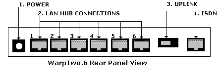
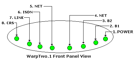
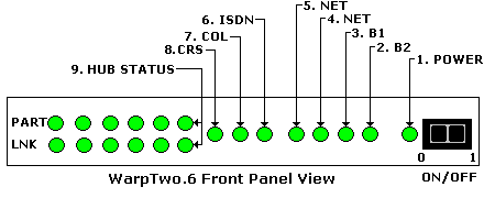
To connect the Router to a power source proceed as follows (NOTE: Numbers refer to Figures 3 and 4 in the ‘Controls’ section):

  1. Connect the Barrel connector from the Wall Transformer to the Power Connector (1) of the Router.

  2. Connect the Transformer to a suitable power socket (2 pin, 110V supply). The Router will draw a maximum current of 1 amp at 9V.

ISDN Line Connections

To connect your Router to an ISDN U line, proceed as follows (NOTE: Numbers refer to Figures 3 and 4 in the ‘Controls’ section):

  1. Connect one end of the ISDN Cable to the Telephone Service Provider’s jack. Your Router has a built in NT1 and DOES NOT REQUIRE an external NT1 unit.

  2. Connect the other end of the cable to the Router U interface connector WarpTwo.1 (2), WarpTwo.6 (4).

NOTE: Your Router DOES NOT REQUIRE AN EXTERNAL NT1 TO FUNCTION. If your Router is connected to an external NT1 it WILL NOT FUNCTION CORRECTLY. If in any doubt contact your service provider and confirm that an ISDN U INTERFACE has been provided.

LAN Connections

To connect your router to your LAN or PC proceed as follows (numbers refere to the diagrams below):

WarpTwo.1

Connect your LAN cable to the RJ45 socket (2)

WarpTwo.6

This product provides an Embedded LAN HUB. Connect your PCs or HUB to the 6 available sockets (2).

Your router may be configured in your LAN network using a variety of methods as described in the next section.

WarpTwo.1 Network Configurations

Figure 1 WarpTwo.1 Network Configuration

The above diagram shows WarpTwo.1 in two possible configurations:

  1. Connected to a single PC (without a HUB) in which case the Router to PC cable MUST be a PC-to-PC (crossed) cable.

  2. Connected to a HUB in which case the Router to HUB cable MUST BE a PC-to-HUB (uncrossed) cable.

WarpTwo.6 Network Configurations

Figure 2 WarpTwo.6 Network Configuration
The above diagram shows connection of your WarpTwo.6 router with a number of possible connections

  1. Router to PC using PC-to-HUB (uncrossed) cables.

  2. Router to HUB using HUB-to-HUB (crossed) cables.

NOTE: Please read carefully the use of the UPLINK switch, which can allow you to connect your WarpTwo.6 Router to a HUB using a PC-to-HUB cable.

Verifying Operation after Power On

Confirm the following steps:

  1. The Router has been plugged into a suitable power socket (2 pin, 110V supply)

  2. One end of the ISDN cable has been plugged into the Router and the other end into the Telephone Service Provider's wall socket.

You will see the following display on the LEDs immediately after applying power:

  1. All LEDS will go ON for approximately 1 second.

  2. LED 2 will go ON for approximately 3 seconds.

  3. LED 3 will go ON for approximately 3 seconds

  4. All LEDS will go ON for approximately 1 second.

If the ISDN line is connected and operational you will see the following sequence of operations on the ISDN Line Status LED:

  1. The ISDN LED (6) will go ON 5 to 10 seconds after connecting the ISDN line, indicating the ISDN line has synchronized at the U interface.

  2. The B1 LED will go ON approximately 5 seconds after the ISDN LED went ON, indicating the switch has accepted the B1 SPID.

  3. The B1 LED will go ON approximately 5 seconds after the ISDN LED went ON, indicating the switch has accepted the B1 SPID.

If the router is connected to a LAN or PC then:

WarpTwo.1

  1. The LINK LED will be ON (7)

WarpTwo.6

  1. One LNK LED on the HUB (1 – 6) will be ON for every active connection.

Contents List Contents List Next Next


Problems, comments, suggestions, corrections (including broken links) or something to add? Please take the time from a busy life to 'mail us' (at top of screen), the webmaster (below) or info-support at zytrax. You will have a warm inner glow for the rest of the day.

Copyright © 1994 - 2025 ZyTrax, Inc.
All rights reserved. Legal and Privacy
site by zytrax
hosted by javapipe.com
web-master at zytrax
Page modified: January 20 2022.