mail us  |  mail this page

contact us
training  | 
tech stuff  | 

products

support home
NetWidget
air-frame

resources

on-line help
tech info
faqs
open guides

If you are happy it's OK - but your browser is giving a less than optimal experience on our site. You could, at no charge, upgrade to a W3C STANDARDS COMPLIANT browser such as Mozilla

WarpTwo Controls and Indicators

The following sections describe the controls and indicators for the WarpTwo range.

WarpTwo.1 (ISDN + Single LAN Connection)

WarpTwo.6 (ISDN + 6 Port LAN HUB Connection)

WarpTwo.1 (ISDN + Single LAN Connection)

Front Panel (LEDs) View

Rear Panel (Connectors) View

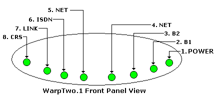
Front Panel (LEDs) View

Key to display

  1. Power. When ON indicates Power is available to the router. When OFF indicates no Power is available to the router.

  2. B1. When ON indicates that the SPID for the ISDN B1 Channel has been accepted and the channel is fully operational. If OFF indicates that the B1 Channel SPID has not yet been accepted. This LED setting is only valid when the ISDN (6) LED is ON.

  3. B2. When ON indicates that the SPID for the ISDN B2 Channel has been accepted and the channel is fully operational. If OFF indicates that the B2 Channel SPID has not yet been accepted. This LED setting is only valid when the ISDN (6) LED is ON.

  4. NET 1. If this LED is steady ON Indicates that the B1 channel is connected to a remote network. If the LED is ON for 1 to 3 seconds then OFF indicates that the B1 channel is dialing but failing to connect successfully (see troubleshooting). If this LED is steady OFF indicates that the B1 channel is not currently connected.

  5. NET 2. If this LED is steady ON Indicates that the B2 channel is connected to a remote network. If the LED is ON for 1 to 3 seconds then OFF indicates that the B2 channel is dialing but failing to connect successfully (see troubleshooting). If this LED is steady OFF indicates that the B2 channel is not currently connected.

  6. ISDN. When ON this indicates that the ISDN U interface has successfully synchronized with the Central Office. When OFF this indicates that the ISDN line has not synchronized (see troubleshooting).

  7. LINK. When ON this indicates that the router is connected to a 10MB Ethernet LAN. When this LED if OFF it indicates that the router is NOT connected to a 10MB Ethernet LAN (see troubleshooting).

  8. CRS. This LED is valid only when the LINK LED is ON. This LED normally flashes when LAN activity is detected.

Rear Panel (Connectors) View

Key to Diagram

  1. Power - Connect the supplied 9 Volt, 1 Amp. 'barrel' type connector here.

  2. Connect to a PC or HUB using a PC-to-HUB (Uncrossed or straight) cable. YOU SUPPLY THIS CABLE. ZyTrax always recommends use of Category 5 or 5e LAN cables for the most reliable performance.

  3. ISDN Connector. Connect the supplied 3 meter RJ45 ISDN U interface cable from the ISDN Wall Jack to this connector.

WarpTwo.6 (ISDN + 6 Port LAN HUB Connection)

Front Panel (LEDs) View

Rear Panel (Connectors) View

Rear Panel Uplink Switch

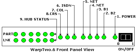
Front Panel (LEDs) View

Key to diagram

ON/OFF 'Rocker' Switch

When the 'rocker' switch is set to the '0' position the Router is not Powered (and the Power LED (1) will be OFF). When this 'rocker' switch is set to '1' position the Router is powered (and the Power LED (1) will be ON).

  1. Power. When ON indicates Power is available to the router. When OFF indicates no Power is available to the router.

  2. B1. When ON indicates that the SPID for the ISDN B1 Channel has been accepted and the channel is fully operational. If OFF indicates that the B1 Channel SPID has not yet been accepted. This LED setting is only valid when the ISDN (6) LED is ON.

  3. B2. When ON indicates that the SPID for the ISDN B2 Channel has been accepted and the channel is fully operational. If OFF indicates that the B2 Channel SPID has not yet been accepted. This LED setting is only valid when the ISDN (6) LED is ON.

  4. N1. If this LED is steady ON Indicates that the B1 channel is connected to a remote network. If the LED is ON for 1 to 3 seconds then OFF indicates that the B1 channel is dialing but failing to connect successfully (see troubleshooting). If this LED is steady OFF indicates that the B1 channel is not currently connected.

  5. N2. If this LED is steady ON Indicates that the B2 channel is connected to a remote network. If the LED is ON for 1 to 3 seconds then OFF indicates that the B2 channel is dialing but failing to connect successfully (see troubleshooting). If this LED is steady OFF indicates that the B2 channel is not currently connected.

  6. ISDN. When ON this indicates that the ISDN U interface has successfully synchronized with the Central Office. When OFF this indicates that the ISDN line has not synchronized (see troubleshooting).

  7. COL. This LED flashes when Collisions are detected on the Ethernet LAN. Collisions are normal on Ethernet LANs but depending on the LAN traffic they should typically be rare (see troubleshooting).

  8. CRS. This LED is valid only when one or more LINK LEDs (see 9 below) are ON. This LED flashes when LAN activity is detected.

  9. Indicates the state of each HUB port. When the LINK LED is ON indicates a valid 10 MB Ethernet connection to a PC or HUB in the corresponding port. When the PART LED is ON indicates an error condition on the interface (see troubleshooting).

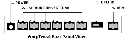
Rear Panel (Connectors) View

Key to Controls

  1. Power - Connect the supplied 9 Volt, 1 Amp. 'barrel' type connector here.

  2. Connect up to 6 PCs using PC-to-HUB (Uncrossed) cables (with RJ45 connectors). Or connect up to 5 PCs and a another HUB (in socket 6) using PC-to-HUB (uncrossed or straight) cables (with RJ45 connectors). YOU SUPPLY THESE CABLES. ZyTrax always recommends use of Category 5 or 5e LAN cables for the most reliable performance. NOTE: See also the Uplink switch when connecting to a HUB or a PC in socket 6.

  3. Uplink Switch. This switch may be used to control the TYPE of cable used when using socket 6 only. See the full explanation below.

  4. ISDN Connector. Connect the supplied 3 meter RJ45 ISDN U interface cable from the ISDN Wall Jack to this connector.

Rear Panel Uplink Switch

This switch controls the behavior of socket 6 ONLY (the socket immediately to the left of the switch). Use this switch as follows:

  1. If using socket 6 to connect a PC using a PC-to-HUB (uncrossed or straight) cable set the 'slide switch' to its RIGHTMOST (PC) position.

  2. If using socket 6 to connect to a HUB using a PC-to-HUB (uncrossed or straight) cable set the switch to its LEFTMOST (HUB) position.

  3. If using socket 6 to connect to another HUB using a HUB-to-HUB (crossed) cable set this switch to its RIGHTMOST (PC) position.

'Slide Switch' setting when connecting to another HUB using a PC-to-HUB (uncrossed or straight) cable. Switch is set in LEFTMOST position.

'Slide Switch' setting when connecting a PC using a PC-to-HUB (uncrossed or straight) cable OR connecting to another HUB using a HUB-to-HUB (CROSSED) cable. Switch set to RIGHTMOST position.

Contents List Contents List Next Next


Problems, comments, suggestions, corrections (including broken links) or something to add? Please take the time from a busy life to 'mail us' (at top of screen), the webmaster (below) or info-support at zytrax. You will have a warm inner glow for the rest of the day.

Copyright © 1994 - 2025 ZyTrax, Inc.
All rights reserved. Legal and Privacy
site by zytrax
hosted by javapipe.com
web-master at zytrax
Page modified: January 20 2022.